
Your shopping cart is empty! Please select the type which you want.
Home > Mall Dynamic > Agertech
Finally, some people understand the "characteristic impedance, reflection, impedance matching"
Cognitive characteristics impedance
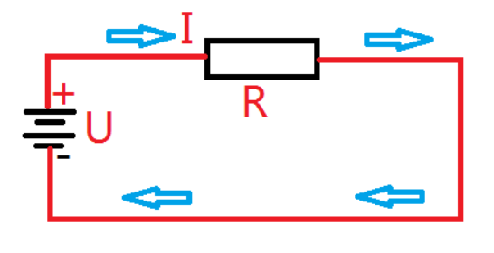
The resistance is a real physical component. Through Ohm's law, we can know that the relationship between voltage, current and resistance, U = i*R.
We analyze the specific relationship between these three through a specific circuit. Please see the simplest circuit diagram below.This circuit diagram has only one power supply and one resistance and some wires.
picture
Of course, the resistance of this resistance can also be measured directly by using a multimeter.
Feature impedance is different. When measuring a 50 ohm characteristic impedance with a multimeter, it will find that it is short -circuited.This requires us to distinguish the resistor (even if it is just 50 ohms) and characteristic impedance.Just like the degree of temperature (degree Celsius) and the angle, it is not a thing.
Everyone understands the physical quantity of resistance, and it will not be explained here.Let's analyze where this characteristic impedance is sacred and under what conditions will this be used.
In fact, the characteristic impedance is a physical quantity that is closely separated from the radio frequency. Before you understand the characteristics of the characteristics, you can first know the radio frequency.We know that radio, mobile communication signals, wifi, etc. are devices that emit signal energy to the outside, that is, the energy is shot out of the antenna, and the energy no longer comes back to the antenna.If you go out, you won't come back.
Well, after understanding the radio frequency, we came to the wire of the specific transmission of radio frequency energy.The radio frequency signal transmitted on the wire is the same. I hope it will not be passed back to the past. If there is energy, if there is energy, it will be revealed that the transmission effect is poor.
For more specific explanation characteristics, I play a thing here: here:
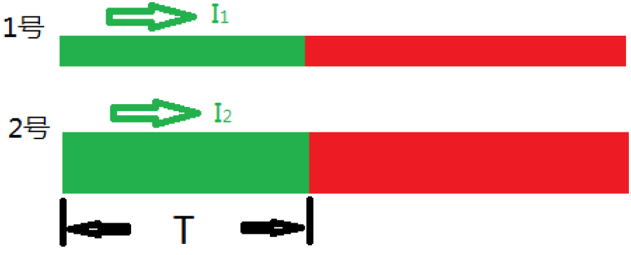
There are 2 guidelines on the same circuit board (assuming that they are two lines, you can imagine how long it is), because the same board, then the thickness of the copper skin of the two conductors is the same thickness.EssenceThe two wires (unlimited long) and thickness are the same. The only difference is the width. Assuming that the width of the 1 wire 1 is 1 (unit), and the number 2 is 2 (unit).In other words, the width of Line 2 is twice as much as Line 1.
The picture below can specify the schematic diagram of the two wires.
As shown in the figure above, if the same RF transmission source is connected at the same time, for a short period of time T, then let's see what is the difference between these two wires.In the same launch source, the output radio frequency voltage of the two lines is the same, and the distance between the radio frequency transmission is the same (assuming that they are all the speed of light, which is actually less than the speed of light).
The only difference is the width of the line, and the line of Line 2 is twice as wider than Line 1, then Line 2 requires 2 times the power of Line 1 to fill the excessive line width area (in fact, the bronze skin and bottom surface of the wire and the bottom surfaceThe capacitor effects generated).In other words: Q2 = twice the Q1.
Because i = q/tTwice).
Well, we know i2 = twice the i1.
Here, we find a mysterious characteristic impedance, why, why, because we know the resistance = voltage/current.In fact, there is a relationship with characteristic impedance: feature impedance = radio frequency voltage/radio frequency current.
From the above we know that the radio frequency voltage is the same, and the current relationship is i2 = twice the i1.
The characteristic impedance of Line 2 is only half of Line 1!
This is what we call the wider line, the smaller the characteristics of the characteristics.
The above is the difference between the characteristics of the characteristics of the characteristic impedance and the resistance, and why the same board, the characteristic impedance is related to the width of the line, it has nothing to do with the length.
In fact, there are many factors that affect characteristic impedance, including materials, wires and bottom plate spacing, and many factors.
The characteristics of the wire are described in popular words (just metaphor), that is, the size of the wire transmitted by the wire transmitted above it.
Know the reflection of the transmission line
Above we assume that the wire is infinitely long, and the actual wire length is limited.When the radio frequency signal reaches the end of the wire, the energy cannot be released, and it will be passed back along the wire.Just shouting to the wall with us, and the voice came back to the wall and came back to generate an echo.
In other words, the situation of the radio frequency signal in our imagination does not reflect back in reality.

As shown in the figure above, if our online end is connected to a resistor to consume (or receive) the radio frequency energy transmitted online.
Some people will ask why the resistance of the characteristics of the wires does not consume energy, and it must be consumed by picking up a resistor?In fact, the wires are only transmitted to energy, and the wire itself does not consume energy or is similar to that does not consume energy (a bit of attributes that want to be capacitance or inductance).Resistance is a component of loss energy.
We found that there are three special circumstances:
When R = R0, the transmitted energy is just absorbed by the end resistance R at the end, and there is no energy reflection back.It can be seen that this wire is wireless.
When R = ∞ (open road), the energy is reflected back, and the end point of the online end will 2 times the voltage of the transmitting source.
When R = 0, the end point generates a -1 times to the source voltage reflection.
Know the impedance matching
Increase matching refers to a working state where the internal impedance of the load impedance and the incentive source is adapted to each other and obtains the maximum power output.
The impedance matching is for RF, etc., and it is not applicable for power circuits, otherwise it will burn things.
We often hear the characteristic impedance of 50 ohms, 75 ohm, etc. How does this 50 ohm come from?
This is agreed, and 50 ohms should be said to be better for general RF circuit transmission.
In other words, our wires and cables need to be 50 ohm because the circuit load is already equivalent to 50 ohm resistors.If you do other impedance values, you do not match the load.The farther away, the worse the transmission effect will be!
Mall Dynamic
